As COVID-19 shut down Tufts this spring semester, our robotics final shifted to coming up with a creative method of moving a ball from the left to the right side of the Zoom video call screen.
The Plan:
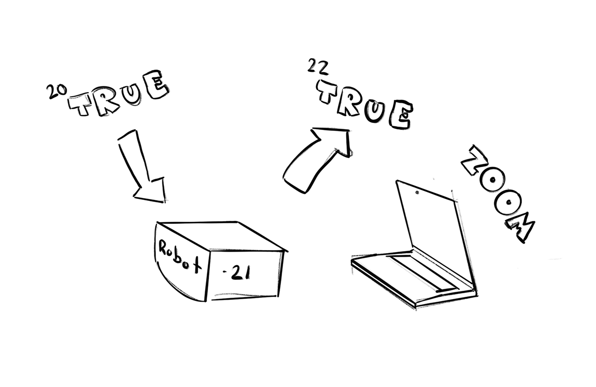
On a Zoom call in Gallery view each student has a place within a 2D grid. One by one moving left to right and top to bottom, each students final project will move a ball from the left to right side of the screen. You can visualize this as one large virtual Rube Goldberg machine.
How will robot actions be synced and remotely triggered?
By monitoring a National Instruments SystemLink dashboard element, boolean type, as the previous robot completes its unique action, the element value will be set to true triggering the start of the next.
Project Approach:
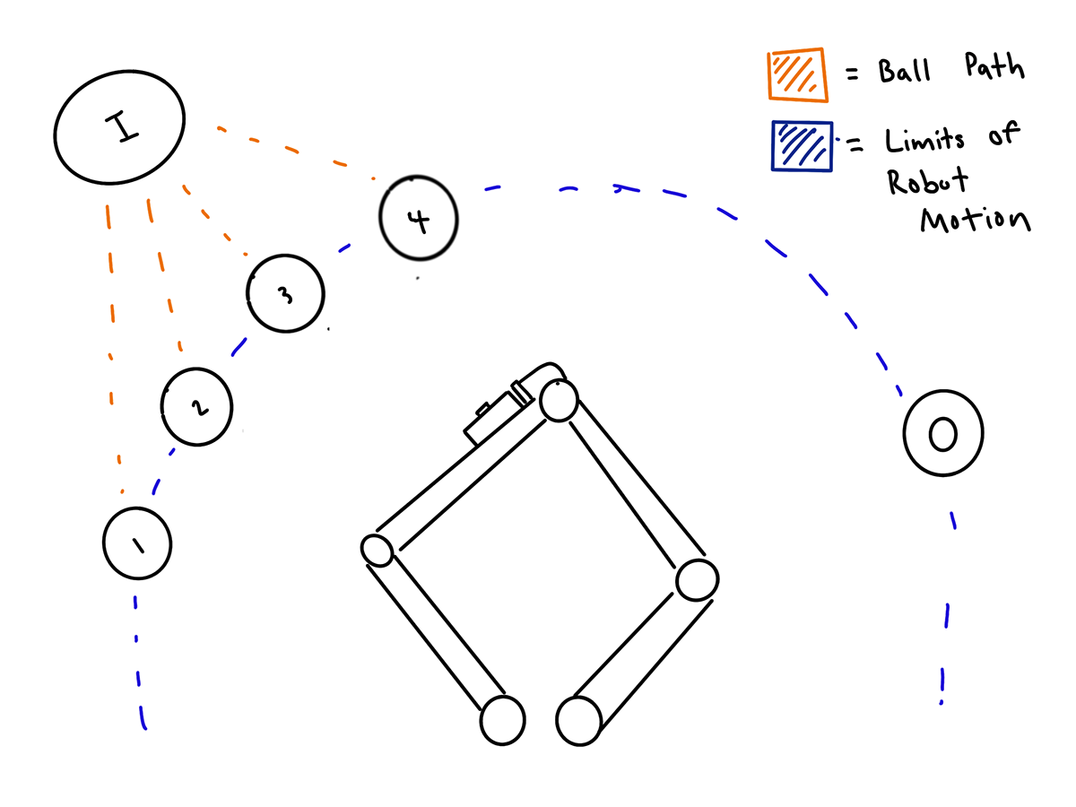
My initial approach in moving the ball from left to right was to utilize a 5-Bar Parallel Robot leveraging a ball recognition machine learning model deployed on a Raspberry Pi Zero. When the start event triggers, a ball would be deployed from input I to a random zone 1-4. Utilizing a Pi Camera end effector, the robot would sweep between zones 1-4, illustrated below, determine the zone occupied by the ball, and move it to system output O.
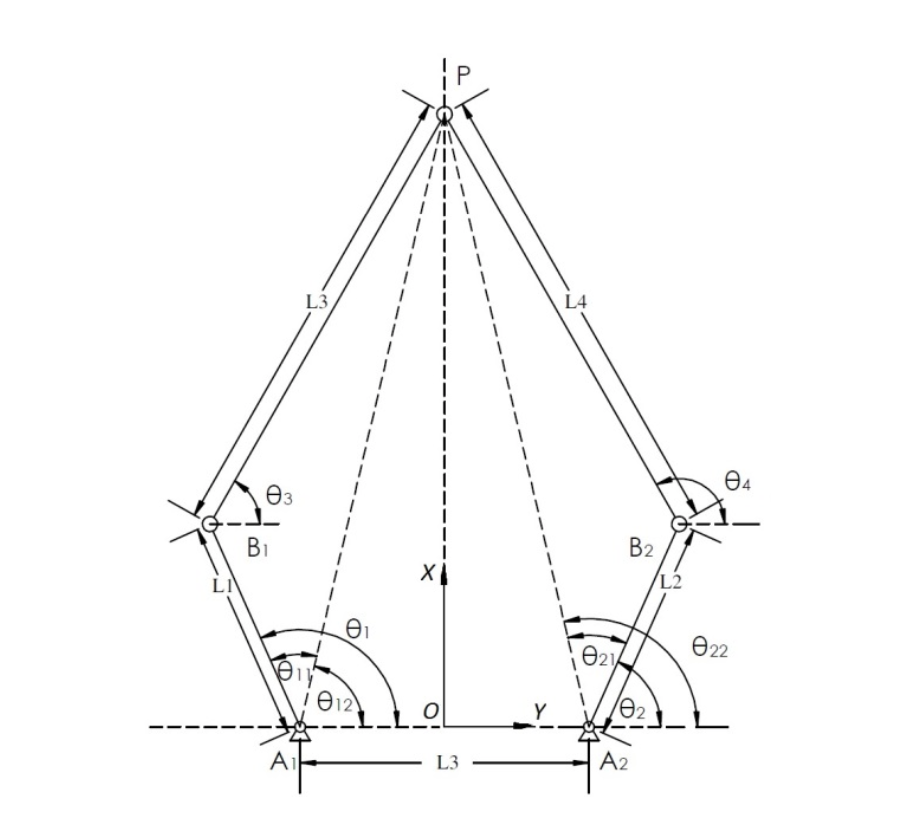
The first step in realizing this approach was to define the inverse kinematics of the 5 bar parallel system. I found a paper on a great geometric approach to determining the joint angles.
The paper outlined four possible orientation cases for a 5 bar system:
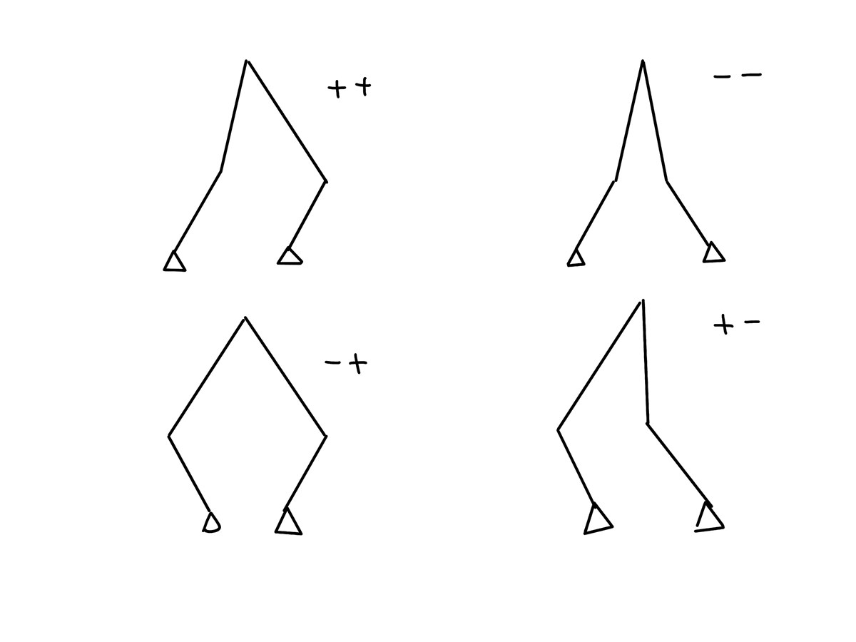
My implementation utilized the -+ model and the following inverse kinematics laid out in the paper laid out below. I reformatted the relevant equations from the paper below.
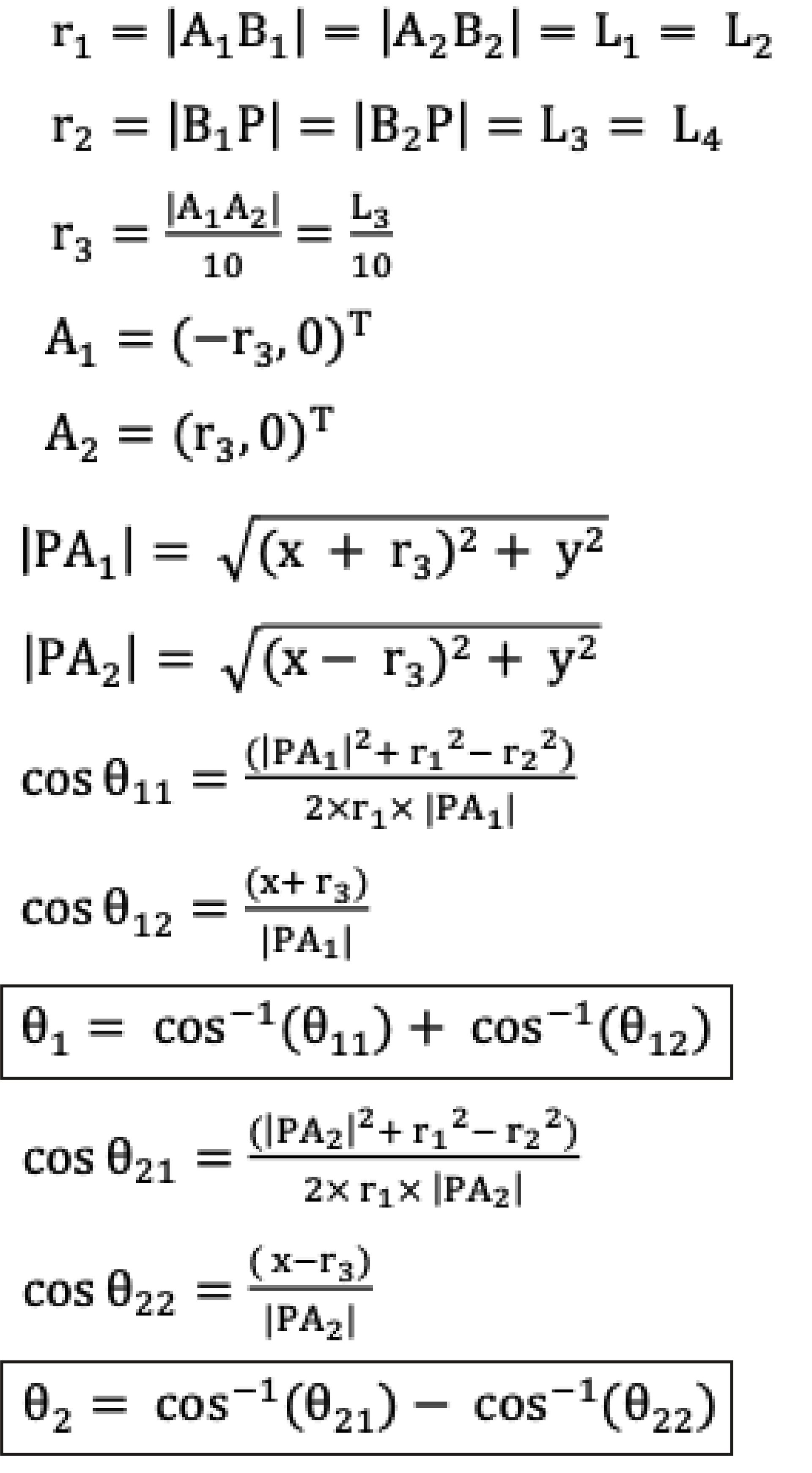
After obtaining the necessary inverse kinematics for the system, I deployed the equations to the EV3 utilizing micropython. My goal with the first prototype was to validate the reach and range of the system and ensure ability to trigger subsystem limit switch
MVP demonstration:
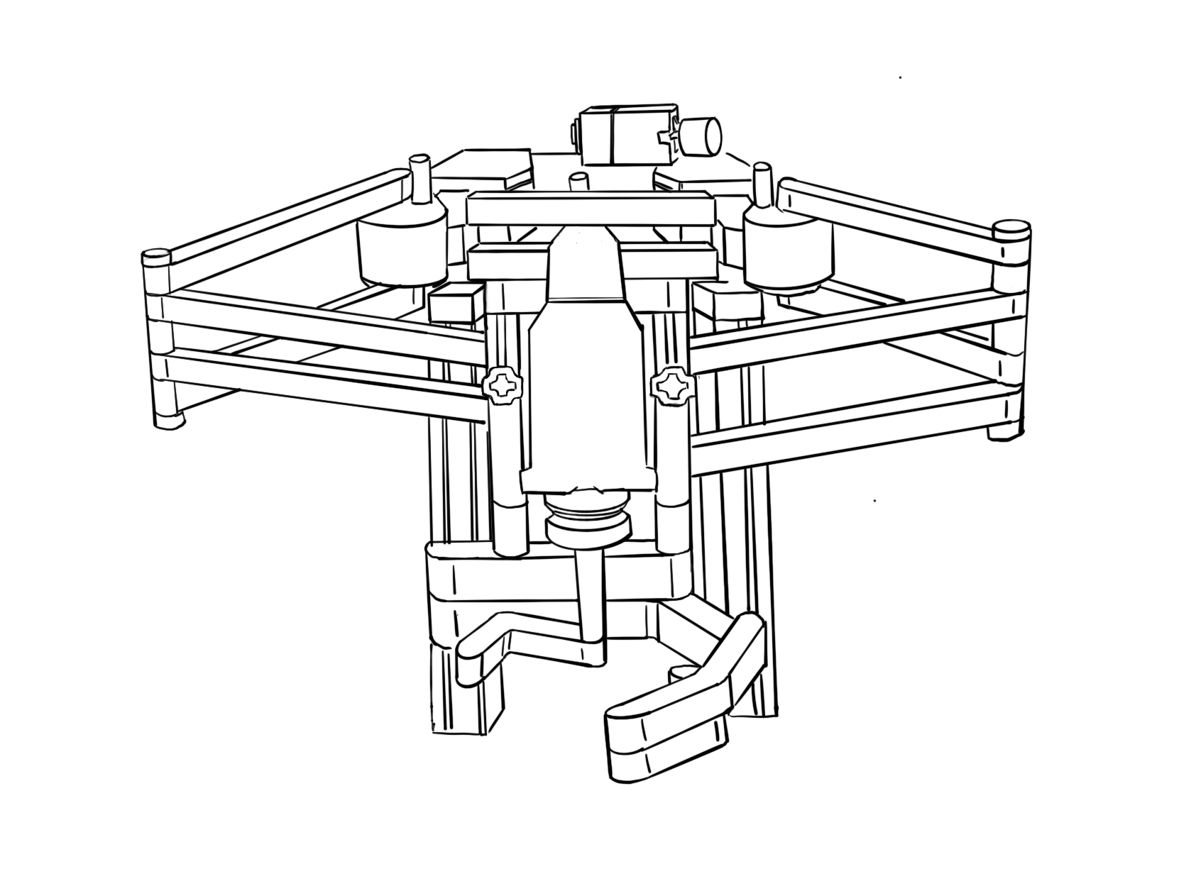
After completing initial prototyping, I revisited my initial sketches and had to devise an alternative method of utilizing the Raspberry Pi camera because the additional moment of camera on end effector the was too much for the direct driven arm.
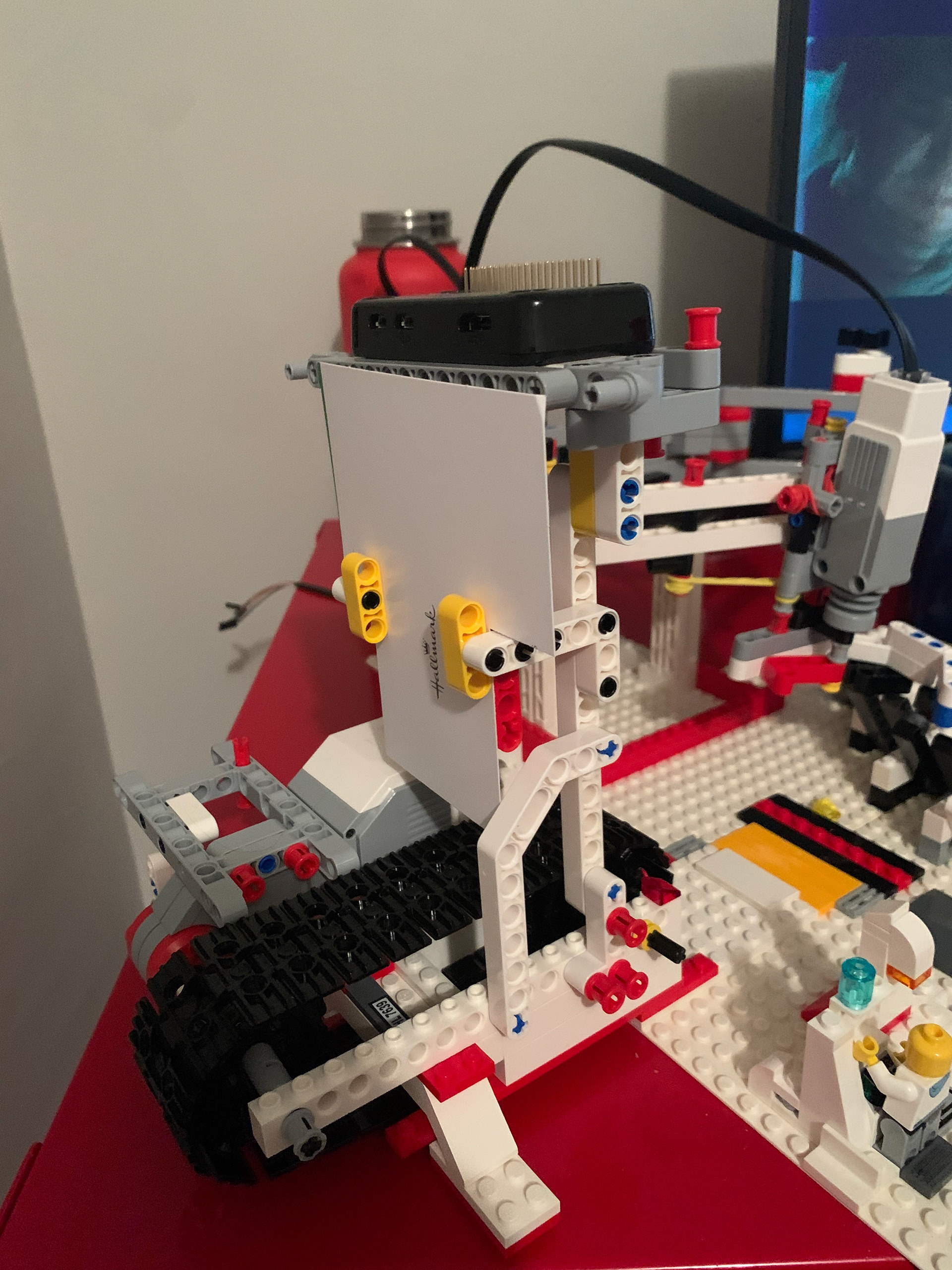
In an attempt to reduce end effector deflection, I doubled each arm of the robot and raised the whole system above the ground to integrate a conveyor belt for ball delivery.
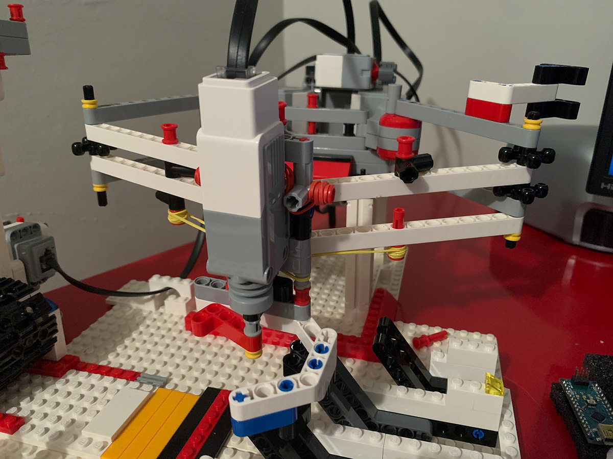
The rubber bands on the new system above keep the claw in constant tension, ensuring that is centered with respect to the arm position.
The push button start for the system was relocated on top of one of the arms of the robot in order to increase the accuracy once all of the field obstacles were in the way.
Even after increasing the rigidity of the system, it was still not strong enough to hold the weight of the Pi camera and the ball payload without considerable deflection.
Instead of mounting the camera on the arm, I decided to design a ball recognition subsystem that triggered when the robot actuated the secondary push-button start.
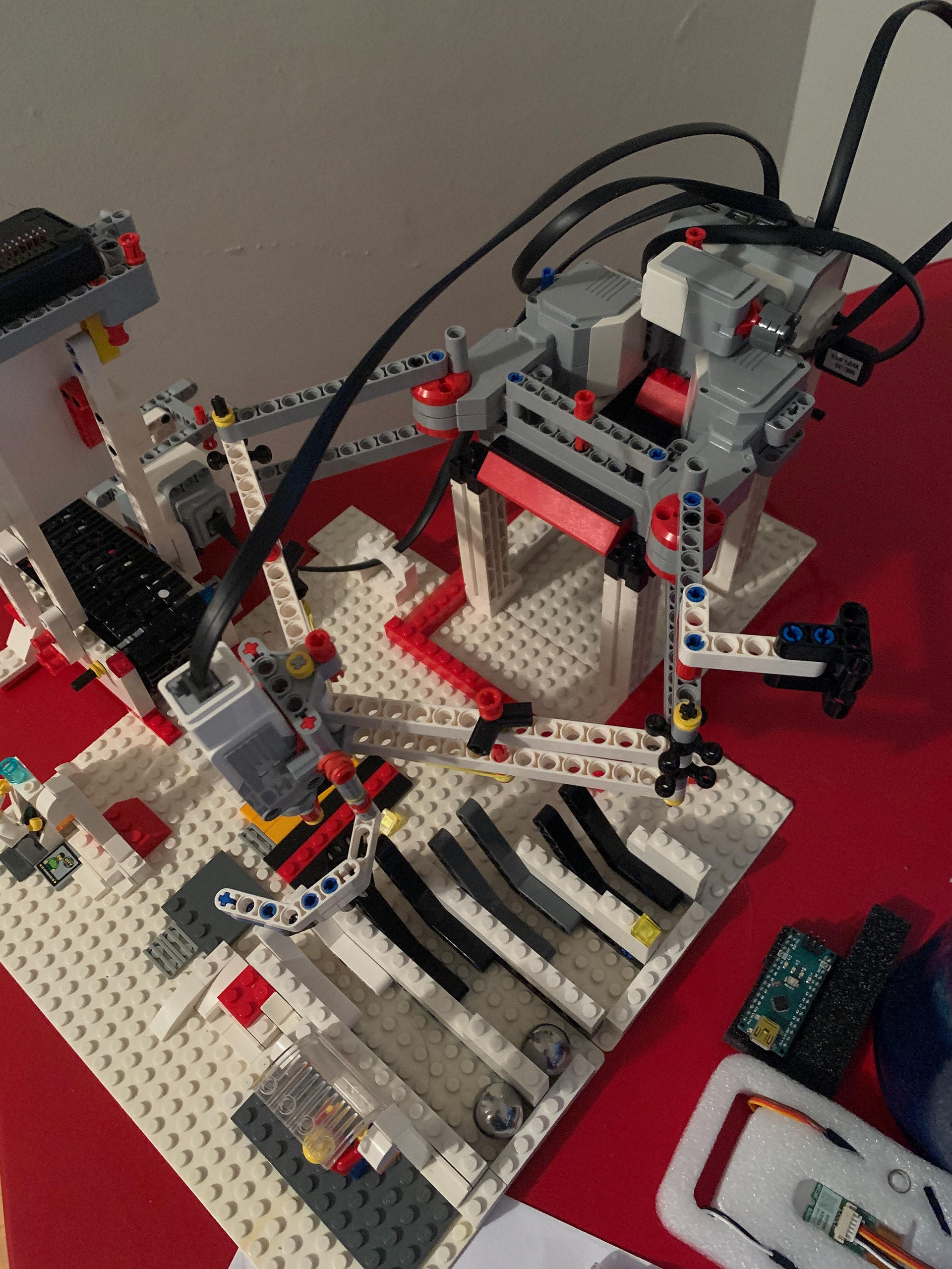
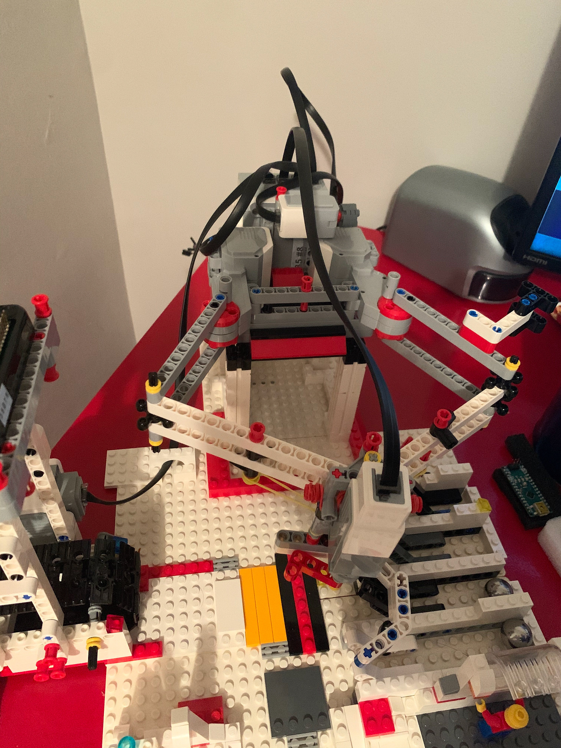
The completed subsystem can be viewed below.
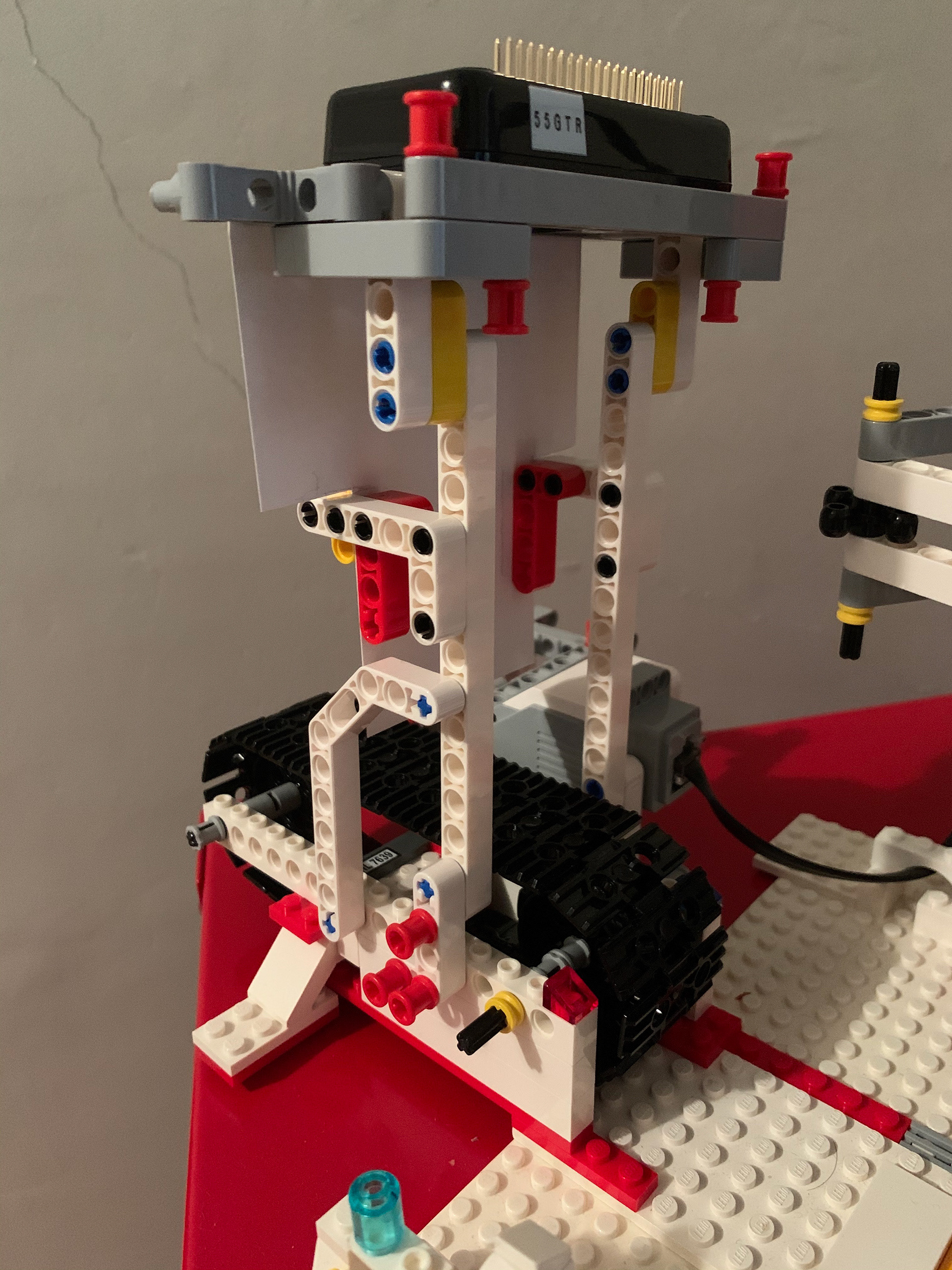
The Raspberry Pi Zero is now connected on the conveyor belt section and suspended in the air so that the claw has space to come and grab the ball off of the belt. An issue I ran into however with the Pi suspended was the large field of view of the camera at that height. Due to this, my Teachable Machines model was failing to produce accurate results in combination with timing the robot claw.
The error was putting a shield, a trimmed card, in between the start of the conveyor belt and the Pi cam effectively narrowing the field of view of the camera and increasing its overall detection accuracy.
Sample Photos from the Raspberry Pi Cam after applying the camera shield:
No Ball Case
Ball Case
Once the camera was setup and taking photos, I trained the robot using Teachable machines. Using a small python training script, I grabbed 40 images of both the Ball and No Ball Case and trained a model. Using Tensorflow, I then imported the Keras model with Python and the ball detection for the Robot was completed.
The Tensorflow code is displayed below along with issues I ran into during the creation of it
Once the Machine Learning was completed, communication for the robot had to be completely setup.
The communication worked as follows:
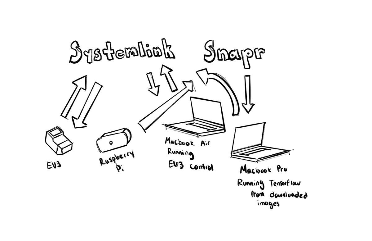
The communication structure can be broken down into 4 sections
1) Raspberry Pi livestreaming to a SNAPR Webserver
2) MacBook Pro running Tensorflow model on images obtained from SNAPR Webserver
3) MacBook Air running EV3 control
4) All of these components are connected to Systemlink Cloud for high level control and communication of the whole system.
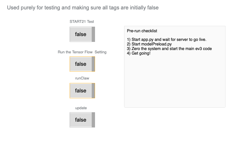
With all of these moving parts in communication, I utilized Systemlink Cloud's Dashboard feature to make a pre-run checklist so that I could ensure I started the system correctly each time. Each of the below True and False sliders live update so the operator is given real-time feedback on state of the system. The testing dashboard can be seen below,
As an intermediary stage in our design process we were tasked to make a mock Kickstarter video, to show off our progress. Mine can be seen below and shows off the work in progress of my system.
The last stage of the design process was tuning the system and the claw design. At first my goal was to create a claw that closed around the ball from the top, but this proved unfeasible with the range of movement in my robot.
My final approach ended up utilizing the conveyor to drive the ball onto the claw. Instead of making the ball rest on a pallet, I made the ball contact the claw in four points so that the only way it was restrained was by the guide arm.
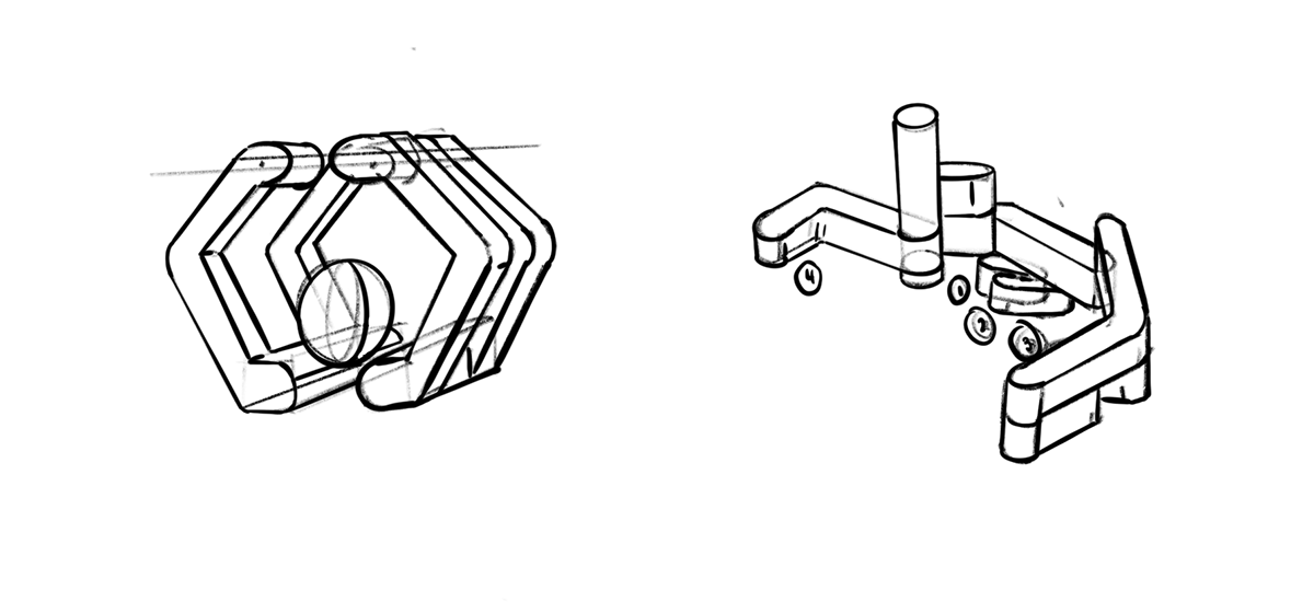
Initial Claw Plan (Left) and Final Claw Plan (Right)
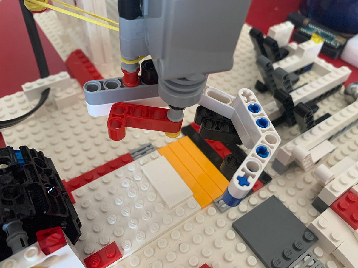
Final iteration of the claw
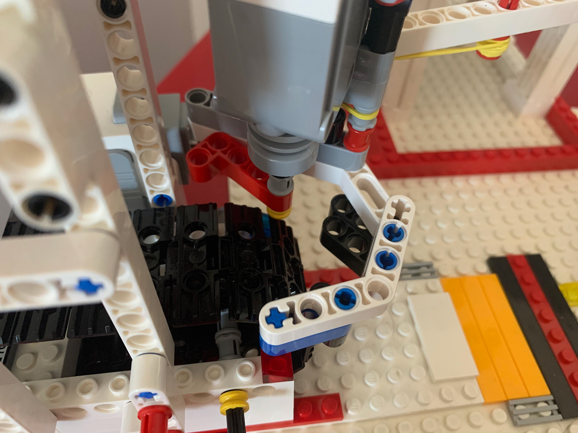
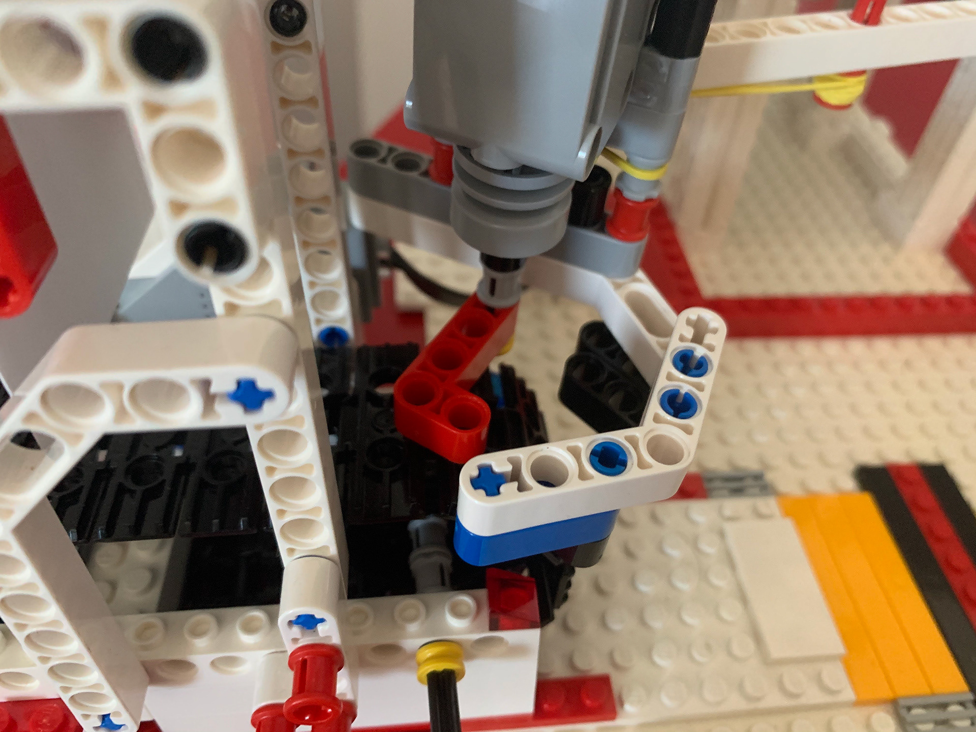
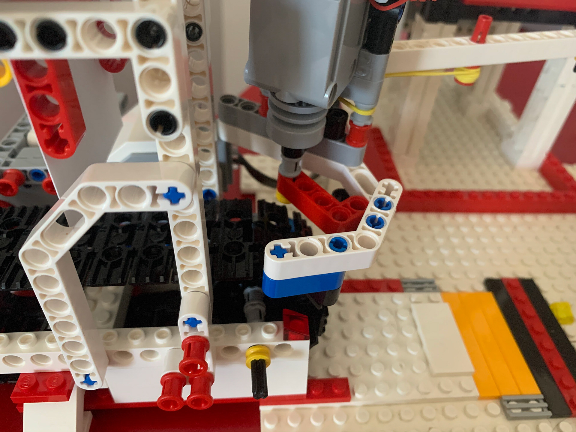
In the final iteration, the claw moves into position and a right angle guide bar moves across the conveyor belt in order guide the ball into the claw. The ball is then restrained with the guide bar and released upon arriving at the desired output lane
After the Kickstarter video I had to figure out issues in my Teachable machines recognition and I was completed with my project. The system is completely repeatable and the full design and operating setup can be seen in my cumulative video below.
System Stats:
The final accuracy of the system out of 15 trials, was around 73%. This metric was deemed by a successful identification, grab, and placement of ball in the final lane. Although this accuracy is not ideal, the only hang up was in the rigidity of the final system. There was a 100% identification rate, but the error came in when the sweep bar would catch and stall on the conveyor itself. This catching error was due to the play in the EV3 motors and was not fixable without further modifications.
All of my code for the operation of this robot is linked below. It is broken up into two sections.
Tensorflow Object Detection run in Python 3.7.7: This code grabs an image from the SNAPR web server and then runs the Teachable Machines Model that was trained off of the sample images above. I implemented a size check on the image in order to make sure I obtained a full image, due to the SNAPR server uploading images at a slower rate than my code download.
References:
1.) Jian, Shengqi, et al. “Five Bar Planar Manipulator Simulation and Analysis by Bond Graph.” Volume 4A: Dynamics, Vibration, and Control, American Society of Mechanical Engineers, 2014, p. V04AT04A026. DOI.org (Crossref), doi:10.1115/IMECE2014-37602.